#A Guitar Tuner and Playback Device using an RP2350
Last semester, I was part of a team that built a Guitar Tuner and Playback device for the final project of the Microcontrollers class at Purdue (ECE 362). This project used an ADC, I2C DAC and an SPI LED Display. This article describes the device, how we built it, and what I learned from the experience.
#Overview
The project consisted of two components: the tuner and the playback device. The following subsections provide a high-level overview of each.
#Tuner
The tuner would capture input from a guitar (how this was done is explained below) and run an FFT (Fast Fourier Transform) on a 1-second sample to determine the frequency. This frequency would be compared to the closest known frequency (i.e. the frequencies of the six strings of a guitar at standard tuning), and the difference between the two would be reported. For reference, the table of known frequencies is provided below:
| String | Frequency (Hz) |
|---|---|
| E2 | 82.4 |
| A2 | 110 |
| D3 | 146.8 |
| G3 | 196 |
| B3 | 246.9 |
| E4 | 329.6 |
#Playback
The project also consisted of a playback device, which would record a 10-second sample of audio. The recorded audio could be played back through a TRRS microphone jack, which was hooked up to a speaker using a standard AUX cable.
#Subsystems
#ADC
An ADC (Analog-Digital Converter) converts analog input to a digital value. In the case of the RP2350 microcontroller, the input is any signal between 0V and 3.3V, and the output is a value between 0 and 4096 (the RP2350 has a 12-bit ADC, hence 0 to 212 − 1). We used this to convert audio signals from the guitar into digital values that we could process. Since the ADC was built in to the microcontroller, we didn’t need to use a protocol to communicate with it.
#DAC
The opposite of an ADC, a DAC takes in a digital value (we used a 12-bit DAC, so 0 to 212 − 1), and outputs an analog signal between 0 and 3.3V. We used this to play back the 10-second audio sample mentioned in Playback. Since the RP2350 has no built-in DAC, we had to use an external one (specifically, the Adafruit DAC7578). We communicated with this DAC using I2C.
#LED
The LED (along with a 4x4 keypad) functioned as the primary User Interface for the project. Upon initialization, the screen would present the user with three options: Tuning, Record Sample, and Playback Sample. Given a keypad input, it would select a mode. The particular LED we chose (the 480x320 ILI9488 TFT-LCD) used SPI to send and receive data.
#Tasks and Challenges
#Capturing Audio Input
The obvious method for receiving audio input is a microphone. We considered this, but soon realized that environmental noise would likely affect our frequency calculations.
I own both an acoustic and electric guitar. On the acoustic, a microphone would likely be the only option, but the electric (like every other electric guitar) has a 0.25-in TS jack. This usually connects to an amplifier or pedal, but I realized that we could process the audio signals directly from it - since the jack is connected to the pickup on the guitar, it’s virtually noise-free, which makes the software’s job a lot easier.
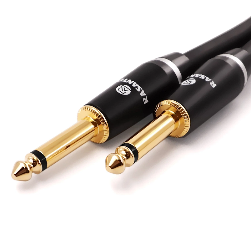
I bought a socket for this connector online, and tested it out. Although it worked, there were two major caveats:
- Magnitude - the output from the guitar was on the order of 100mV, far too feeble to do any meaningful processing on.
- Center - The output was centered at 0V. Recall that the ADC needs an input signal between 0 and 3.3V - it can’t process negative voltages.
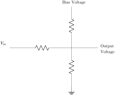
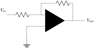
To fix these, we would need to shift the signal to center it at 1.65V (half-way between 0V and 3.3V), then scale it so that it ranged from 0V to 3.3V. This was all done in hardware - a bias adder (using a voltage divider) was used to add the offset, and an inverting amplifier was used to amplify it.
#Storing the Input
Now that we had the input in the correct range (0 to 3.3V, centered at 1.65V), we had to store it. This was easy - the ADC peripheral on the RP2350 allows you to write consecutive measurements to a buffer through DMA. Since the response from the tuner needed to be in real-time (or as close to it as we could get), we figured that a 1-second buffer was enough.
Next question: At what rate do we sample? Too fast, and we would need too much space (which is a luxury on the RP2350) to store a 1-second sample. Too slow, and we wouldn’t be capturing the shape of the signal accurately. The lower bound is specified by the Shannon-Nyquist Theorem, which I have paraphrased here:
If a function x(t) contains frequencies no higher than β Hz, it can be completely determined using a minimum sampling rate of 2β per second.
Let’s say the maximum frequency we care to sample is 500 Hz. Using this theorem, we would need a sampling rate of at least 1000 samples/sec.
We chose a maximum frequency of 1000 Hz (approximately the 20th fret of the E4 string), giving us a minimum sample rate of 2000 samples/sec.
We chose to collect 10,000 samples which results in a sampling rate of 10 kHz for a 1-second sample. This seemed to work perfectly well for our use case.
#Processing the Input
After storing the input, we had to determine its frequency. A Fast Fourier Transform (FFT) is the most common way to determine the frequency of a signal, and that’s the method we chose. We used the kiss-fft library for this.
We also double-buffered our inputs, to ensure that we weren’t losing data while we processed a sample. This involved creating two 10,000-entry buffers. We fill one, and while we’re processing it, we redirect the ADC to fill up the second one. When that one fills up, we redirect the ADC to the first one, and process the second one.
Once we had the frequency, we simply compared it to the closest known frequency, and printed out how far the user was from that frequency. The device would also use PWM (pulse-width modulation) to simulate the known frequency, and play it out loud.
#Playback
This part was much easier to implement than the tuner. We simply stored samples into a ten-second buffer (using the sampling rate from earlier, that meant a 100,000-entry buffer). When the user requested playback of the audio, we sent the buffer via I2C to a DAC, which converted it into an audio signal that could be routed to the TRRS jack.
Before sending it to the jack though, we had to amplify it: the speaker draws way too much current for the DAC, so we needed some way to boost the power of the signal. An LM386 Audio Amplifier was our choice: we just followed the datasheet and stuck it in between the DAC and the TRRS jack.
#Conclusion and next Steps
My favorite part of this project was the opportunity to tie a personal interest (music and guitars), to an academic one (embedded systems). The signal processing aspects were new to me (we hadn’t really covered it in class), and I loved learning about the intricacies in storing and processing signals.
One of the cool techniques I learned about was Parabolic Fitting: a traditional FFT gives you a bin of frequencies, with the magnitude of the signal at each frequency bin. For example, the FFT might tell you that the signal has a magnitude of 4 at 70 Hz, 3 at 80 Hz, and 3 at 150 Hz, with negligible magnitudes everywhere else. Rather than picking the bin with the largest magnitude as the frequency, this method suggests considering the two bins surrounding the bin with the highest frequency. Then, fit a parabola through these three points (the two aforementioned bins, and the one with the highest frequency) and choose the peak of the parabola as your frequency. This allows us to interpolate frequencies with greater precision.
The next steps would likely be to move the playback buffer to some external storage like an SD card. This would allow us to store many orders of magnitude more samples, and we could even save them to a file on the SD card, with the ability to select a specific file to play back from. We could also extend the project to incorporate an effects pedal, adding distortion, reverb, and other effects to the signal.
Ultimately though, I had a blast working on this project, and I hope to continue working on it in my free time.